Components
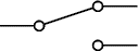
Initial circuit

Initial circuit
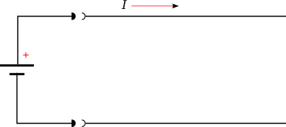
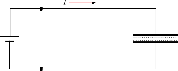
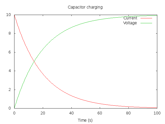
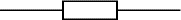
What happens when the battery is connected to the wires (Figure 1) ? Neither the battery nor the electrons can 'know' what is at the far end of the wires; what current flows ? The answer is that the initial current depends upon the characteristics of the wires - it depends upon their impedance alone. This current flow will happen, even if the far end has nothing connected - i.e. it is an open circuit. As electrons accumulate at the end of one wire and a deficit develops at the end of the other, an electic field develops which opposes further current flow. This effect is usually so small that we do not notice it, but we can make it more pronounced, as in Figure 2. Now, the ends of the wires are large plates. There is a large area over which electrons can spread and much more current will flow until the electic field (potential difference) across the plates matches that of the battery and the electron flow ceases. Plotting a current/time graph produces an exponential decay; with each unit of time, the current flow decreases as the capacitor voltage approaches that of the battery (Figure 3).
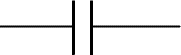
Capacitor circuit
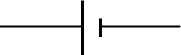
Capacitor
The larger the capacitor, the greater the quanity of charge it holds for any applied voltage and the greater the voltage, the greater the amount of charge which will be stored on its plates for a given voltage (Equation 1).
Q = CV
The ability of a capacitor to store charge is used in devices such as the defibrillator, but they are often used in another way, as electrical filters
Applying a DC voltage to a capacitor results in a brief current flow, but this quickly declines towards zero. So capacitors block the flow of direct current. If an alteranting current is applied, then repeated charge/discharge cycles will occur and a current will continue to flow. The larger the capacitor and the higher the frequency, the larger this current. Clearly, this phenomonen is something like resistance in that for any given voltage, the current is related to the size of the capacitor. In addition, however, we need to consider the effect of frequency. This is termed reactance and is as described in equation 2. When plotted, it produces the hyperbolic curve show in Figure 4.
Xc = 1 / 2πfC
Capacitor frequency / current graph
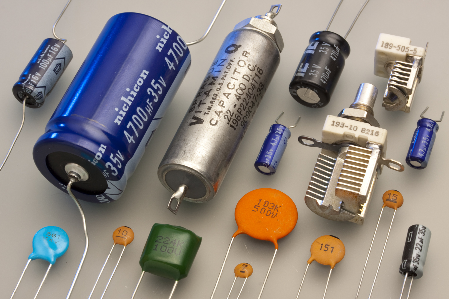
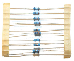
Appearance of capacitors

A fuse is a safety component which is designed to fail when the current passing thorugh it exceeds a certain value. The simplest fuses are pieces of wire the diameter of which is chosen such that the heating effect of a current raises the temperature of the wire above its melting point. Since the power dissipated in a resistor is I2R, the temperature in the fuse-wire rises very rapidly when its design current is exceeded. Some devices normally draw high currents for very brief periods of time. To accomodate this, 'slow-blow' fuses can be designedd with a high 'thermal mass' - that is with an additional mass of metal (Fig. 6 images 2 and 3) to absorbs heat and delay the rupture of the fuse.
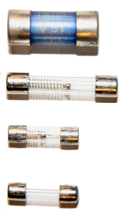
Fuses

An inductor is a device which depends on the interaction between a current and a magnetic field. At its simplest it can be a coil of wire, but the magnetic effects can be enhanced by winding the coil around a material with ferro-magnetic properties
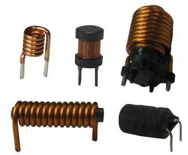
Appearance of inductors
When an inductor is connected to a power supply, a current begins to flow. When a current flows through a wire, it creates a magnetic field and as the current rises, so the magnetic field grows. This creates a moving magnetic field which induces a current in the inductor. The induced current tends to opposes the applied current.
When power is first applied, the rate of increase of the magnetic field is as its greatest and only a small current will flow. As the current increases (i.e. tends towards the maximum which can flow in the circuit), the rate of change of the magnetic field slows and more current is able to flow. Thus, Thus an inductor tends to oppose any change in the current flowing through it; it can be expected to allow direct currents, but block alternating currents (the opposite properties to those of a capacitor). The higher the frequency of the alternating current and the larger the inductor, the less the current which flows. The equation for inductive reactance is as show in figure
XL = 2πfC
Offer a fixed relationship between current and voltage as defined by Ohm's law. The proportionality constant, R, is measured in Ohm's (Ω)
V = IR
Resistors
Chemical source of direct current. Strictly, a battery is a collection of cells.

By tradition, the reference point for measuring potential differences. Since much of our power supply is earthed, it is important when considering electrical safety.
Many biological signals are very small so must be amplified to be useful (e.g. ECG or EEG). As the signal is amplified, so too is noise (random, undesirable fluctuations) which causes distortion. In interpreting the amplified signal, maintaining a high margin between the signal and noise is important (think of an ECG with a great deal of noise from muscle activity) - this is the signal to noise ratio (SNR).
One way in which this can be improved is by selective amplification of relevant frequencies only. This can be achieved using filters. Filters can pass only low frequencies, only high frequencies or only a range of frequencies, so-called low-pass, high-pass or band-pass filter. The properties of inductors and capacitors fit these requirements rather well !
In simple terms, a placing a capacitor at the input to the amplifier provides a high-pass filter (capacitors block DC but pass high frequencies). Similarly, placing an inductor on the input would produce a low-pass filter and using a combination of inductors and capacitors can provide band-pass.
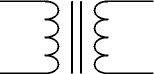
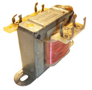
A transformer
A transformer acts like a pair of inductors (coils) placed so close together that their magnetic fields overlap. One coil is defined as the primary and one the secondary.
When an AC current is applied, the constantly changing magnetic field induces a current in the secondary coil. Since the magnetic field acts on each turn in the secondary, a current is induced in each turn (and so a voltage appears across each turn) and the total voltage across the secondary winding represents the sum of the voltages across each of the turns.
i.e. the secondary voltage is dependent on the primary voltage and the ratio of number of turns in the primary and secondary coils (Equation 5).
Vs = Vp * Ns / Np
General form of a linear equationBy changing the ratio of primary to secondary turns, a transformer can provide a step-up or step-down in voltage. In the power distribution grid, this is useful because energy losses can be reduced by increasing the supply voltage and decreasing current flow (power flowing through the system does not change P=VI, but heat losses decrease as P=I2R).
A much more common application is to provide low voltage power supplies from the mains. A 20:1 turns ratio would provide a 12V AC supply from a mains-connected transformer.
Connecting the transformer in Fig.9 to a signal generator, gives the output in Fig.10.
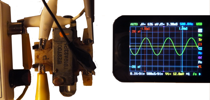
Step down Vpp=0.32V (0.1V/div)
Connecting the secondary winding of the same transformer to the same signal generator (i.e. step-up), gives the output in Fig.11.
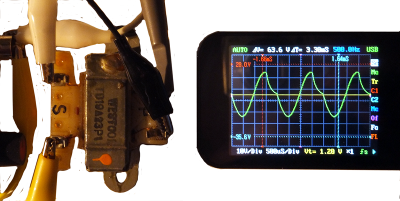
Step Up Vpp=39V (10V/div)
This suggests that the transformer has a turns ratio of around 11
If a 1:1 turns ratio is used, then the secondary voltage will be the same as the primary. On initial consideration, this seems pointless, but in fact it is very useful and very widely used. Although the secondary voltage is the same as the primary, there is no electrical connection between the two i.e. a transformer provides electical isolation between the primary and secondary windings (see electrical hazzards for an explanation). This principle is used across the telephone system and computer networks, every device being connected via an isolating transfer, so that electical faults do not comromise the system.
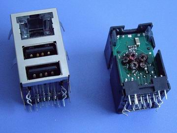
Isolating transformers visible in a standard computer network socket.
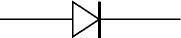
A diode is made of semiconductors. It allows current to pass in only one direction and has non-linear current-voltage characteristics.
Diode current-voltage characteristics
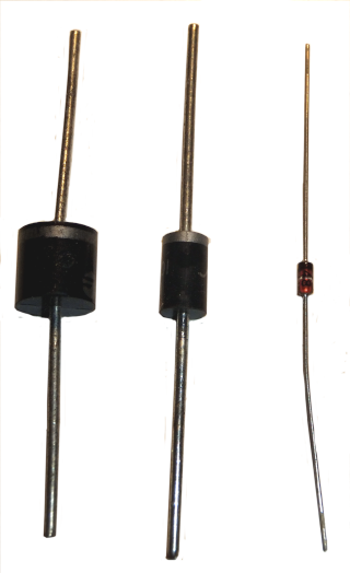
Diodes
Since a diode on allow current to flow in only one direction, it can convert alernating to direct current. Using a single diode can provide 'half-wave rectification, whereas 4 diodes give 'full-wave rectification'.

Diode rectification
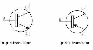
Transistors are semiconductors, like diodes and like diodes they allow one-way flow of current and have non-linear voltage-current characteristics. Unlike diodes, they have a third terminal. When a small current flows through this third terminal, it is capable of controlling a much larger current between the other two. As a result, transistors can act as amplifiers or switches.
Transistors
Imagine connecting a conventional meter (Fugure 8) to a biological system in order to measure a signal. The current it would draw would be so large as to distort the measurement. The ideal solution is to make a measurement when no current is flowing into the measuring system and this is the key to the importance of the Wheatstone bridge (Figure 9).
The voltage across AE and BF must be the same (Vbat). If the meter is removed, then it is obvious that the current through (R1+R2) and (R3+R4) depend on their resitances (Ohm's law). Equally, if R1=R3 and R2=R4, then the voltages at C and D must be the same. But this is also true when the ratio of R1:R2 is the same as R3:R4
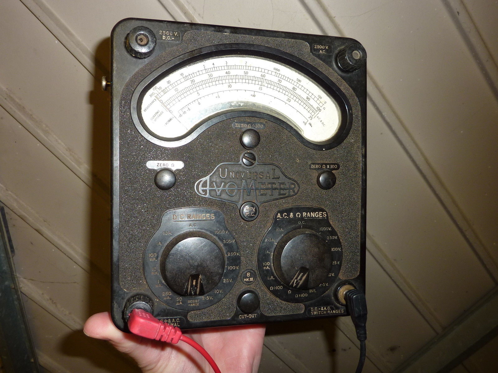
Moving goil meter

Wheatstone bridge
When the voltage at points C and D is equal:
VR1 = VR3 and VR2 = VR4
By Ohm's law, V=IR, so
I1R1 = I3R3 and I2R2 = I4R4
BUT, when VC=VD, there is no voltage difference across the meter and Im=0. This means than I1=I2 and I3=I4
Substituting:
I1R1 = I3R3 and I1R2 = I3R4
I1 = I3R3/R1 and I1 = I3R4/R2
Dividing through by I1 and rearranging:
R1/R2 = R3/R4
You are more likely to see a Wheatstone bridge drawn as in Figure 10 (and note that the resistors are labelled differently). The principle remains unchanged. At balance, the ratios of the resistors is the same, so in Fig 10, R1/R3 = R2/R4. Here R4 is an unknown resistor. However, R3 is measurable and we know the values of R1 and R2. Thus we can calculate the value of R4 even if it cannot be measured directly.
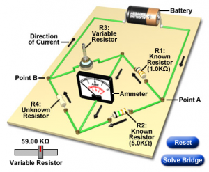
Wheatstone bridge
An inductor:
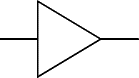
Amplifiers:
The Wheatstone bridge circuit