For the simplest anaesthetics, as in Figure 1, a patient can provide the energy to move anaesthetic gases.
Clover apparatus with chloroform Anaesthetics: J.T. Clover. Credit: Welcome Collection.
This approach is very limitted and fails as:
The requirements for supplemetal gases increase (a source of compressed gas quickly become the only practical way in which to deliver what is required)
The circuit resistance increases (the patient can no longer sustain the work of breathing
There is a need for muscle relaxation.
As a result, we are used to having gasses supplied in cylinders or via pipelines. Since the volume of a cylinder is limitted by practical considerations, it is unsurprising that the pressures within cylinders are as high as possible (e.g. oxygen 137 bar / 2000 psi) to maximise the quantity of gas which they contain. By contrast, a pipeline need only run at the lowest pressure (e.g. 4 bar) needed to reliably deliver the required flow.
In order to control the supply of a compressed gas we require devices which will limit pressures (regulators) and flows (valves). Because we use gases from sources with very different pressures, these may be cascaded i.e. a high pressure regulator is used in series with a low-pressure regulator.
These systems will be discussed in the followng sections
Cylinders are a convenient means of providing access to small amounts of gas, but they must be regarded with caution. Some cylinders contain gases at high pressure, whilst others contain liquids and vapors. A rupture may allow the contents to expand violently and some may also support combustion (oxygen or nitrous oxide). As a result, a great deal of effort is expended to make cylinders safe.
Material: molybdenum or chromium steel. These are strong and corrosion resistant.
At the time of manufacture 1% of cyclinders are cut into strips for testing.
At intervals, each cylinder is subject to high-pressure, hydraulic testing (steel cylinders every ten years and composite cylinders every five years). It is filled with water pressurised to 200-250 bar to confirm its ability to withstand these pressures and measure the elastic recoil of the metal. For safety, this occurs in a water tank. The cylinders are also inspected endoscopically. The date when the next test is due appears on the plastic disc attached to the neck of every cylinder (see below).
Next test date appears on the cyclinder neck. In this case, May (Green label), 2018 (Grey label).
Fuseable cylinder plug. The low melting-point material in the centre of the plug melts as the temperature rises, allowing the cylinder to vent.
Fuseable seal. The low melting-point material in in the seal melts as the temperature rises, allowing the cylinder to vent.
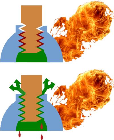
No matter how strong the cylinder, if its temperature is raised sufficiently, then rupture becomes inevitable. In order to prevent this, a low-metling point material is used to allow controled venting. In the US, this generally takes the form of a fuseable plug. In the UK, the sealant between the valve and cyclinder body fulfills the same purpose. Clearly, the venting gas may exacerbate any fire, but this remains a much better options than an explosion.
In recent times, composite cylinders have appeared (e.g. BOC medical, industrial). These consist of a steel or aluminium inner liner, externally reinforced by a fibre-glass. Kevlar or carbon-fibre winding in epoxy resin. They have the advantage of being lighter and stronger than steel cylinders, can be filled to higher pressures and include integral regulators and valves. Unfortunately, even quite minor damage to the fibre-reinforcement can result in failure, although literature reports indicate the regulator as the initial seat of several fires ([1], [2]). Although in widespread use, the cylinders should be treated with even greater care than standard cylinders and they should be turned on away from the patient and only transported in cylinder holders (i.e. NOT on flammable bedding where a devastating fire can take hold within seconds).
Identification
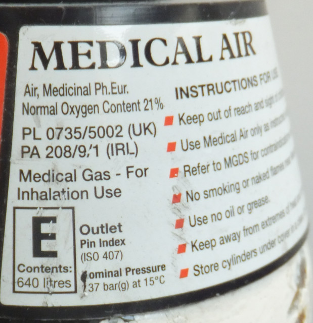
Although gas cylinders are colour coded, the correct way to identify the contents is via the cylinder label. This records the followinf information, as shown in the images below.
Product name, chemical symbol and form
Product specifications
Product license
Cylinder size code and contents in l
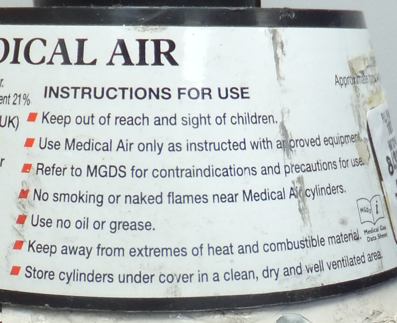
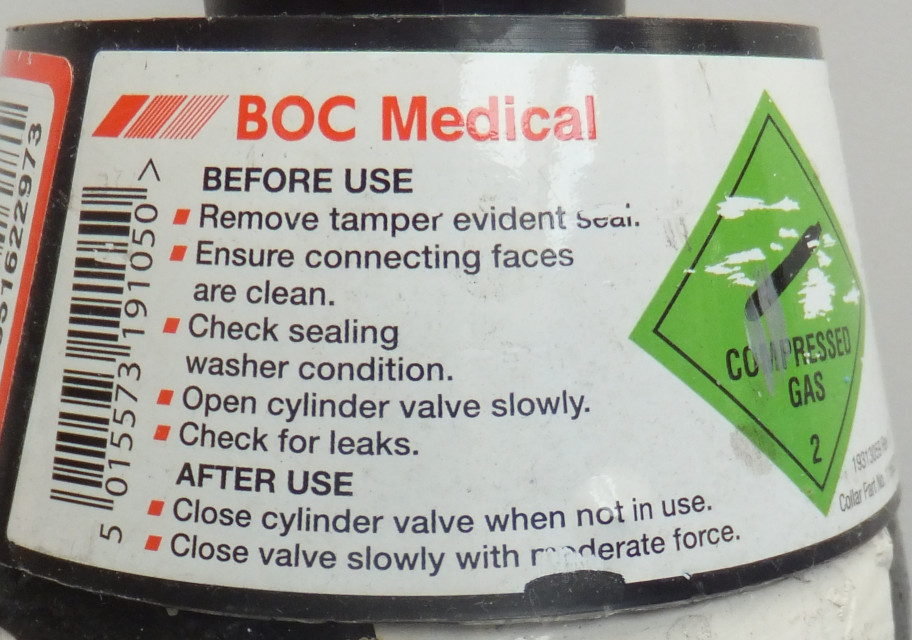
Instructions for handling and use
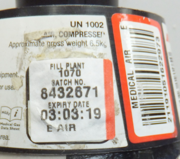
Batch label showing the batch number, expiry date, size and gas
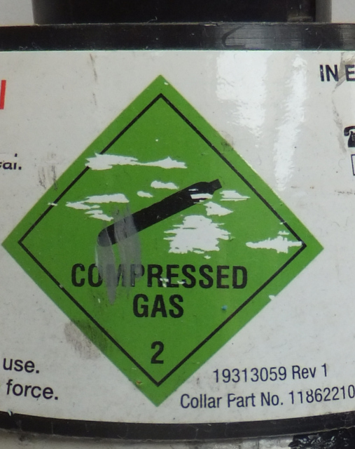
Hazard warning diamonds
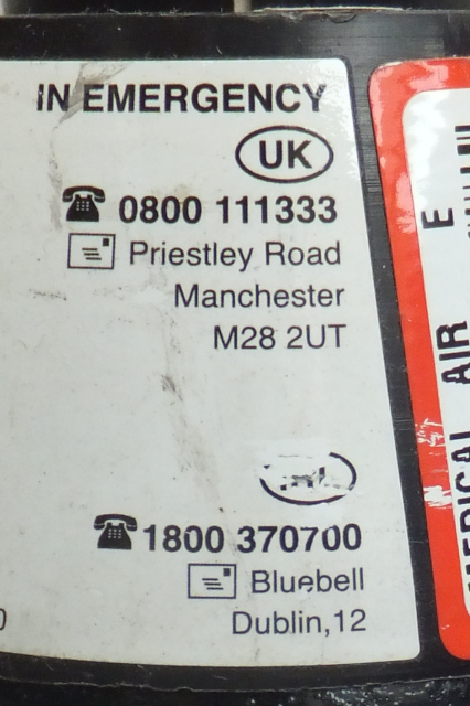
Emergency contact details
Cylinder labels
Cylinder sizes
Cylinder sizes are described by alphabetic codes, the commonest of which are shown below
Code
Construction
Water capacity (l)
Valve type
Outlet
Dimensions (mm)
Oxygen
Nitrous oxide
Air
Entonox
CO2
Heliox
Neck
Content
Gas
Liquid
Gas
Gas
Liquid
Gas
CD
Composite
2.0
Handwheel
Integral Schrader/firtree
520*100
230 bar
460 l
N/A
N/A
N/A
N/A
N/A
D
Standard
2.3
Key
Pin-index
535*102
137 bar 340 l
44 bar 900 l
N/A
137 bar 500 l
50 bar 900 l
N/A
E
Standard
4.7
Key
Pin-index
865*102
137 bar 680 l
44 bar 1800 l
137 bar 640 l
N/A
50 bar 1800 l
N/A
F
Standard
9.4
Key
Bullnose
930*140
137 bar 1360 l
44 bar 3600 l
137 bar 1280 l
137 bar 2000 l
N/A
N/A
HX
Composite
10.0
Handwheel
Integral Schrader/Firtree
930*140
230 bar 2300 l
N/A
N/A
N/A
N/A
200 bar 1780 l
Common cylinder properties.
Valves
In order to contain the gas in the cylinder, there must be some form a valve. For medical gases, you are likely to encounter:
Pin-index (below)
Bull-nose (below)
Integral with regulator. Standard with composite cyclinders
Handwheel - unusual in anaesthetic practice.
Opening a valve without a regulator in situ used to be a standard way to clear any dust or debris before connecting the cylinder. This was referred to as 'cracking' the cylinder and is dangerous. It is easy to rupture an eardrum by standing in-line with the escaping gas, so great is the pressure. Modern cylinders are supplied with dust seals which are removed immediately before use.
>Pin-index
Cylinder yoke with pins
Cylinders are connected to the machine via a yoke (Fig. 7). It is essential that the correct gas is connected in each position. In order to prevent the wrong cylinder from being inserted, the yokes employ a system of pins which will only engage with cylinders with corresponding drillings (Fig.7).
Cylinders have matching drillings in any of 7 positions.
The pins are numbered in a clockwise direction with reference to the yoke (anti-clockwise when considering the cylinder drillings) and run in the order 1237456 (Fig. 8).
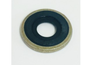
A Bodok seal
Simply tightening the screw tensioner (Fig. 5) is not enough to provide a gas-tight seal between the metal surface of the cylinder valve and that of the yoke. A washer is required. Unfotunately, given the high pressure involved, a simple washer would be likely to fail. The solution is to use a washer with a peripheral metal reinforcement. This is know as a 'Bodok seal' (Fig.9). The neoprene from which the seal is made, is resistant to combustion even when exposed to the adiabatic heating which occurs as the cylinder valve is opened.
Bull-nose valves
These are found on larger clyinders (F and above) and require the attachement of a regulator.
Bull-nose connections.
Cylinder contents
A cylinder may contain a compressed gas or a vapour in equilibrium with liquid. Although the 'packaging' appears identical (a cylinder), they can have very different properties.
Property
Compressed gas
Liquid/vapour
Pressure
Varies in proportion with the cyclinder content If PV = nRT, then at a contant temperature and fixed cyclinder volume, P ∝ n, so we can determine the cyclinder content by measuring pressure.
Pressure remains constant until the liquid has evaporated. The liquid exists in equilibrium with a saturated vapour. As we draw off vapour, more liquid evaporates to replace it. As a result, pressure remains constant until all of the liquid has evaporated. N.B. A fall in pressure may be seen with rapid rates of gas consumption; this will happen as the cylinder cools and the SVP drops. This still provides no information about the cylinder content.
Weight
Is not a practical method to determine content An E-size oxygen cylinder weighs 5.4kg empty (the 'tare' weight). Full it contains 680l of oxygen with a mass of 0.680*1.429 (vol in m3*density) = 0.97kg. So, from full to empty, its mass changes by only 15%.
Weight can be used to determine content An E-size nitrous cyclinder contains 1800l of N2O with a mass of 1.8*1.9775 = 3.56kg. So, from full to empty, its mass changes by 60%. Weighing liquid-filled cylinders is a practical method of determining their content, though not used in clincal practice.
Position
Unimportant
Cylinder MUST be used upright Some CO2 cylinders are designed to provide liquid CO2. In these 'LF' cyclinders, a 'dip tube' runs to the bottom of the cylinder allowing liquid to be drawn off preferentially. In all other cases, it is the vapour which we want; using the cylinder in anything other than a vertical position can result in liquid entering the equipment to which it is connected. As it evaporates, the delivery of a large volume of gas would result in the delivery of unexpected (potentially hypoxic) gas mixtures.
Filling ratio
N/A
N2O / CO2 0.75 (temperate) / 0.67 (tropical climates) As it warms, a liquid will
expand. Were a cylinder completely filled with liquid, then any
subsequent temperature rise would result in a pressure rise likely
to result in rupture. In order to avoid this, liquid cylinders are
incompletely filled. Unfortunately, the definition used is
confusing (mass of substance contained / mass of water which the
cyclinder could contain, both at 15°C) and requires the densities of the liquids to be considered when trying to understand what this means for the liquid content of the cylinder. A nitrous oxide cyclinder in a temperate climate will be filled to around 95% of its liquid capacity (based on PubChem data).
Differing behaviours of liquid and gas-filled cylinders.
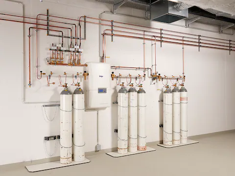
Manifolds
The weight of cyclinders makes it impractical to continue to increase the sizes used as we need ever more capacity. As a result, the use of manifolds became common, connecting cyclinders in groups to increase to amount of gas available. It also has a more subtle benefit in that it not only makes available more gas, but increases the rate at which it can be delivered as the cooling effects of decompression are spread over a group of cylcinders and regulators, allowing much greater gas flows than would be possible from a single cylinder, no matter how large.
One disadvantage of manifolds is that all of the cyclinders tend to empty at the same time. In order to prevent sudden gas failure, they are generallyconfigured in 'banks', so that as the 'active' bank is depleted, the 'reserve' can be selected. The empty cyclinders can then be replaced allowing the bank to assume the role of 'reserve' and the procedure to be repeated when required. For this to work safely, gas failure alarms are required so that the banks can be switched over as supplies run low.
A manifold showing duty, reserve and emergency cylinder banks
Liquid cylinders
Manifolds work well in small sites and when delivering vapours (N2O). As demand increases, the delivery of oxygen becomes a particular problem. In order to handle the volumes required, it becomes necessary to use sources of liquid oxygen, but with a critical temperature of -118.5°C this is not easy. An early solution was the use of 'liquid cylinders' which are heavily insulated cylinders, fixed in location and filled remotely by a tanker.
Since the liquid oxygen is stored in an enviroment well above its critical temperature, it will tend to 'boil off' continuously. As a result, the cyclinders are designed to vent when a safe pressure limit is reached. However, this 'boiling off' of gas carries energy away, cooling the cylinder. As a result, with effective insulation, a liquid cyclinder may lose only 2% of its content over 24hrs and provided that there is a demand for the gas, all of this can be used.
Cryogenic liquid systems
A cryogenic liquid oxygen system
As demand for gas (almost exclusively, oxygen) increases, bulk cryogenic tanks become the only practical solution. This allows the delivery of liquified gas by tanker and the system can meet very high peak demands. The layout of a typical system is as shown below.
A VIE and main evaporator
The main component is the 'vacuum insulated evaporator' (VIE) which is a double-walled pressure vessel. The inner vessel contains the cooled, pressurised, liquified gas, while the space between the two vessels is maintained at high vacuum. Since no insulation can be perfect, some heat will enter the vessel and vaporize some of the liquid. This can be vented by pressure relief valves (which will open at a pre-determined pressure and then close as the pressure falls), but often the gas can be used immediately and is simply passed into the pipepline. In case of failure, there is also a 'rupture' valve in the system. This will break if the pressure in the system becomes excessive and discharge the entire contents of the VIE.
In order to ensure that the pressure within the VIE does not fall below its operating level, a valve will release liquified gas into a 'pressure maintaining vaporizer' when the VIE pressure decreases. This uses environmental heat to vaporize the gas and maintain the required pressure.
A similar principle is used when a demand is placed on the VIE. Liquified gas is allowed to enter the main vaporizer where it warms and feeds the main gas piplelines. As this process occurs, the vaporizer cools and you will often see them with a thcik coating of ice.
A differential pressure guage provides an indication of the quanity of liquid in the tank (since it is measuring the differential pressure between the top and bottom of the VIE, it provides a measurment of the height of the fluid column above the bottom of the tank NOT the 10.5bar working pressure of the system). However, this is not regarded as a reliable enough for filling. Instead, a pipe built into the VIE and placed at a fixed position opens as part of the 'tri-cock filling valve'. As the fluid level in the VIE rises, eventually the pipe opening is submerged and it will vent liquid rather than gas. This is the indicator that the VIE is filled to its maximum capacity.
For more details, this is a link to a US cryogenic gas supplier which describes the process very well.
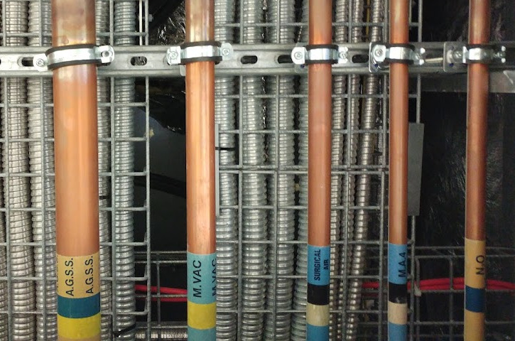
Distribution system
Part of the distribution system at RLH.
Medical gases are distributed through the hospital via a system of semi-hardened copper pipes. The diameters are chosen so as to minimise the pressure drop from the source to point of use and as a result, these will decrease from very large (76mm) to small (11mm) as the gases move from source to an individual outlet.
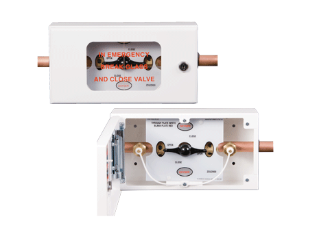
An 'Area valved supply unit'
Valves are placed at various location throughout the pipeline network in order to allow isolation of areas when work is required or in case of emergency. 'Area valved service units' (AVSU) are placed at entrances to wards and theatre areas and you will see these throught the hospital. The valves are placed in lockable boxes, with glass access panels which can be be broken in case of emergency (e.g. pipeline rupture or fire) to allow anyone to shutoff the gas supply. As can be seen in the figure, the AVSU also contains NIST valves which allow access to the pipeline on both the upstream and downstream sides of the valve. These can be used to introduce inert gases to purge the pipeline when work is requried or to allow the connection of an alternate gas supply to support the downstream network when the valve must be closed to allow work on the proximal pipeline system. During the extreme supply demands associated with COVID, we used this system to connect additional oxygen cyclinders to support the pipeline pressure.
Distal to the AVSUs, every area should have an alarm panel which shows the status of the medical gas supply. The display is very simple and should show 'Normal', 'High' or 'Low' pressure (usually set at +-20% of nominal). When the supply pressure falls outside of the limits, there should be both audible and visual inidications of a fault. The sounder can be silenced, but only for a period of 15 minutes, after which it is re-enabled. When the supply returns to normal, the alarms reset automatically.
When work is done on the system, it must be explicitly authorised using a 'Permit to work' and clinicians in the affected areas should be aware of the potential for supplies to be disrupted. In order to maintain the purity of the gas supply and protect the network, all joins are copper to copper and made using fluxless brazing. As part of the process, the pipe is filled with nitrogen and although this should have been purged from the network before it is returned to use, it underlines the importance of the machine check - unusual gas mixtures should be detectable during calibration !
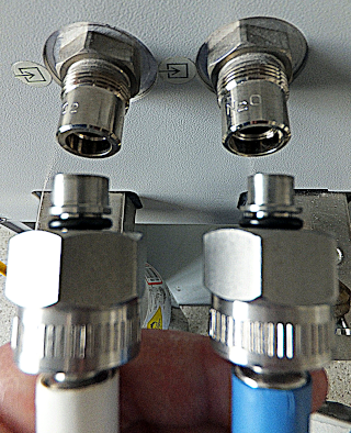
Terminal outlets are relatively complicated in their design. They consist of a termination assembly which is permanently connected to the pipeline. This contains a check valve which operates automaticlly when the second component, the Schrader assembly, is removed. As a result, it is possible to change the Schrader assemblies in service without shutting off the gas supply. This is important because the Schrader assemblies are subject to a greater level of wear and small leaks are not uncommon.
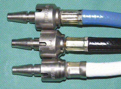
Schrader probes - collar-sizes vary with gas, but the probes are uniform.
The Schrader terminal assemblies are designed to be gas specific. This is done by using collars of specific sizes on the probes, which slot into grooves on the terminal assemblies. The Schrader probes themselves are of a standard size.
Flexible hoses are colour coded and provided pre-assembed with Schrader probes and NIST (non-interchangeable screw-thread) assemblies crimped in place in order to prevent accidents.
NIST connectors - the probes differ, but the screw assemblies are uniform.
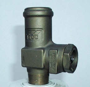
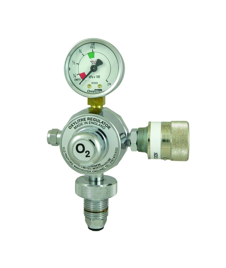
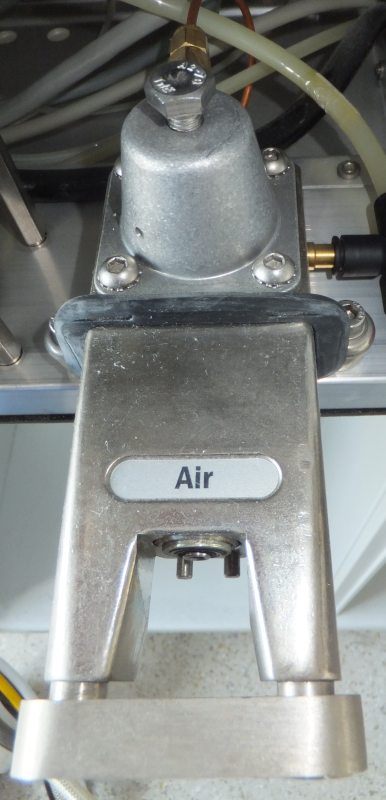
A high-pressure cyclinder regulator in an anaesthetic machine. The narrow-bore copper pipe coming from the back of the regulator supplies the pipeline pressure gauge.
Pipelines delivers medical gases at a pressure of 400kPa (4bar). Cylinder pressures are much higher (O2 and air 137bar and N2O 44bar) and yet both must supply the same systems despite wide variations in demand. In order to achieve this, reulators are required. These mechanical devices will accept variable input pressure and provide a constant output pressure across a range of flows. A simple design is show below.
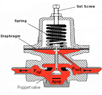
Schematic of a simple pressure regulator
When the cylinder is opened, the force pushing the poppet valve upwards is Pcyl*Apop. If we tighten the set screw such that the downward force provided by the spring just opens the poppet when Pout is at the desired pressure, the system will tend to maintain this pressure. If Pout falls, then the upward force on the diaphragm (Pout*Ad) will fall. This allows the spring to push the diaphragm downwards and opens the poppet valve wider. Conversley, if Pout rises, then the upward force on the diaphragn (opposing the spring) increases and tends to close the valve. In use, tthe forces exisit in balance, so the valve is help partically open, maintaining Pout at the desired pressure.
The area of the diaphragm (Ad) is shown as being much larger than that of the poppet valve seat (Apop). This is important because we want the position of the diaphragm to be controled solely by the balance between the force of the spring balanced against Pout*Ad. In reality, Pcyl*Apop also plays a role; this is just an unfortunate side-effect of the design but means that as the cylinder pressure falls, the valves tends to open more and Pout will rise. By making Ad much larger than Apop, this effect is minimised since changes in Pout produce much larger movements of the diaphragm than do changes in Pcyl.
Anaesthetic machines generally use piped gases and provide a cyclinder as an emergency backup. Cylinders should be checked during the machine check and their valves should then be closed to prevent them from being emptied inadvertently. An additonal safety feature is provided by careful setting of the high-pressure (cylinder) regulator; this is usually set to deliver an output pressure of a little below pipeline pressure. In this way, when the pipline is connected, the output of the cylinder regulator is exposed to a higher pressure than it is set to deliver and it should close preventing accidental use of the cylinder.
In applications where very stable pressure control is required, regulators may be cascaded so that a 'first-stage' regulator, receiving widely varying input pressures (e.g. 0-137 bar from a cylinder) supplies a 'second-stage' regulator with a much more closely controlled (e.g. 9-11 bar) gas supply. The second stage regulator can now be expected to operate within much closer tolerances. In the anaesthetic machine, however, we have a slightly different requirement. Here we genrally want the machine to be able to deliver constant flows rather than constant pressures and as a result, the gas from the cylinder regulator or pipeline is fed to a flow-meter.
In the anaesthetic machine we generally want to be able to control gas flow and so the term 'flow-meter' generally refers to two, linked components; a needle valve and a variable area, constant differenial pressure flow-meter.
Needle valves
A needle valve
Needle valves allow very precise control over the flow of high pressure gas into the flow-meters. The valve block is usually a separate component so that it can be replaced if damaged. Because of the delicacy of the valve, it shouls never be over-tightened and will often have 'stops' to prevent this from hapening.
Where nitrous oxide is used, the needle valves may be modified to prevent the creation of an hypoxic mixture. This system uses a pair pf cog-wheels on the oxygen and nitrous valves, linked by a chain, such that a minimun oxygen:nitrous ratio is always maintained. Unfortunately, the introduction of low-flow systems renders this safety device ineffective.
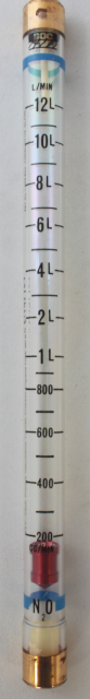
Given the complexity of the name, it is hardly surprising that the trade name 'Rotameter' has been adopted as a generic term to describe this type of device (Fig. 22). A cylindrical bobbin is suspended in a tapering tube (usually glass). As can be seen in the highly stylised figure below, at the bottom of the tube, the gap between the bobbin and wall is reminiscent of a long, thin pipe where laminar flow may be expected. As a result, flow is described by the Hagen-Poiseuille equation (equation 1) and the pressure drop is related to the viscosity of the gas (equation 2). Further up the flow-meter tube, the appearance much more resembles an orifice where turbulent flow is to be expected. As a result, ΔP is now related to the density of the gas (equation 4) and the square of the flow ! It is only with very careful design that the gradations on the flow-meter tube can be set at useful intervals (often a log scale).
Q = ΔP / 8ηl
ΔP ∝ ηQ
At the bottom of the tube viscosity is relevant
Q ∝ 1 / √(ΔP * ρ)
ΔP ∝ 1 / (ρQ2)
At the top of the tube density is relevant
The design of the Rotameter
The rotameter includes a number of design features intended to enhance safety
The bobbin has slots cut into it so that the flowing gas tends to make it rotate. This centres the bobbin in the gas stream (improving accuracy) but also makes it easy to see that it has not become stuck
The top of the rotameter includes a 'stop' so that the bobbin remains visible at maximum flow (or even above) and there can be no doubt that a very high flow of gas is running. This is important when using gases which migh produce an hypoxic mix.
The rotameter tube is often coated with a gold film. This allows static charge to leak away easily and help to prevent the bobbin from becoming stuck.
By careful design, the bobbin moves much further at low flows than high. This makes it possible in a single rotatmeter to make delicate adjustments at low flows while still being able to deliver high flows. An alternative approach is to use cascaded rotameters, the first covering a low-flow range. When the bobbin moves off-scale on this tube, the next rotameter will be at the bottom is its range (e.g. two rotameter one with a range of 0-1l and one with a range of 0-15l).
The fact that a rotameter tube must be designed with reference to both the viscosity and density of a gas means that it can only be used with that gas. Rotameters are NOT interchangeable.
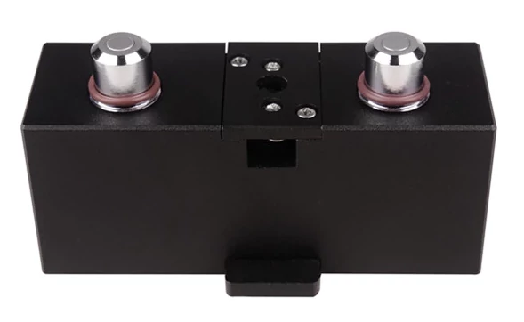
The first anaesthetic machines assembled the basic components which had come to be standard for anaesthetic use; they tended to be monolithic. In order to allow flexibility, the backbar developed to allow vaporisers to be connected and disconnected at will. Initially, these connections were similar to those in the breathing system (push fit), but gradually a more sophisticated system developed.
The TEC backbar
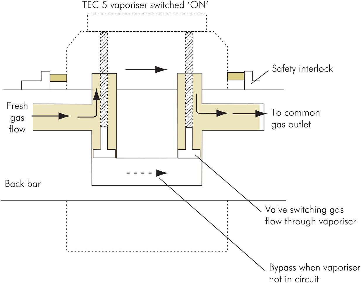
The TEC backbar allows vaporisers to be added at will and can support multiple vaporisers or none. In order to achieve this, it has mounts are self-sealing valves. In the 'up' position (no vaporizer), gas simply passes along the backbar. In the 'down' position (vaporizer present), gas is diverted via the vaporiser.
A schematic of the TEC backbar
Manufacture and storage of gases and vapours / safety
Might belong with individual gases
Individual gases
Oxygen
Oxygen is obtained through fractional distillation of liquified air. This produces large quantities at very low prices, such that we use oxygen with little thought. In hospital, the supply is cheaper and more plentiful than that of air.
Oxygens support combustion and at high pressures or conentrations, some material which would not normally burn do so vigorously. Often very little energy is required to start a fire. On opening a cyclinder, the adiabatic heating which occurs as the residual gas in a regulator is compressed can easily ignite any grease which might have been applied inappropriately. A spark is enough to cause bedding, clothes or hair to burn furiously.
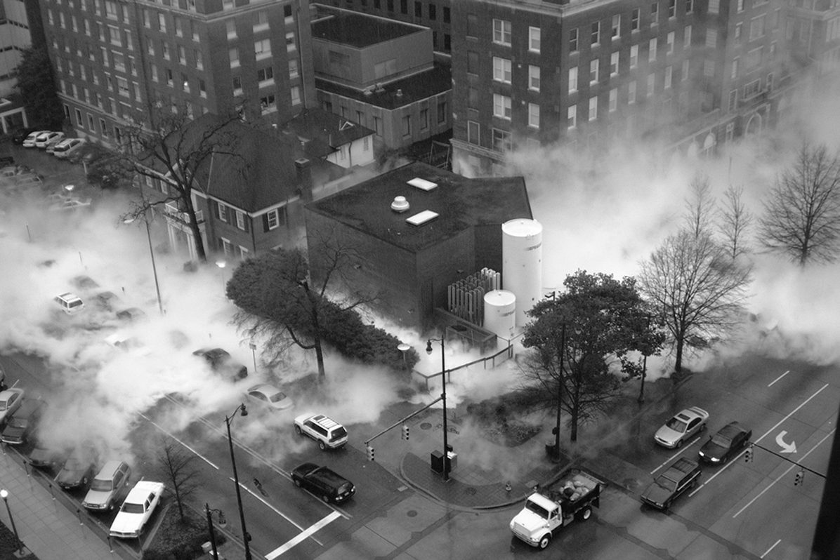
Handling liquid oxygen brings additional risks. Skin will stick to and freeze to any of the cold surfaces exposed to the liquified gas. The drastic expansion which occurs as the liquid vaporizes demands that it be handled in areas which are well ventilated and clear of any combustible materials. Just walking on asphalt which has been drenched in liquid oxygen can be enough to cause ignition - as a resul, you will always see a VIE mounted on a concrete base. Nonetheless, the volumes of gas which can be released in event of failure are so large that the repercussions can be widespread, as shown in the photgraph below.
Falures in oxygen delivery systems are so rare, that we give them little thought. Nontheless, they do happen and we are so dependent on having immediate access to a reliable supply, that is is important to consider what to do in an emergency.
Nitrous oxide
Nitrous oxide is supplied either as a piped gas from a cylinder manifold or from individual cylinders. It is present as a compressed liquid at a pressure of 44bar. As vapour is drawn from the cylinder, more of the liquid nitrous oxide evaporated to maintain the equilibrium. Since evaporation requires energy, the cylinder temperature will fall and it is common to see a 'frost line' on small (D or E) cylinders used at high flows. This temperature drop will be associated with a fall in the cylinder pressure, but this cannot be used to gauge content. If the cylinder is allowed to re-warm, the pressure will return to 44bar, even if it almost empty. The only way to determine content is by weight and this is not particularly practical as the weight of gas is small by comparison with that of the cylinder. In the days before pipeline supplies, the solution was to have two cylinders on all machines - one in use (the 'duty' cyslinder) and one as a reserve.
Manufacture
Nitrous oxide is produced by the controlled heating of ammonium nitrate to 240–250°C in a decomposition reactor. It is crucial to control the temperature to prevent explosive decomposition !
The reaction is
NH4NO3 -> N2O + 2H2O
The nitrous oxide and water vapor mixture is collected and the the hot gases cooled. This condenses and removes most of the water vapor. The remaining gas is then purified by 'scrubbing', which involves passing it through chemicals which remove impurities such as other nitrogen oxides. Common scrubbing materials include solutions of alkalis like sodium hydroxide (NaOH) to neutralize acidic byproducts. Finally, the gas is dried further using desiccants (e.g., silica gel or molecular sieves) to remove residual moisture.
The purified nitrous oxide is compressed and cooled to liquefy it for storage. It is also tested to ensure it meets medical standards.
Air
Air is supplied in cylinders or via a pipeline. The cylinders have the same properties as their equivalents for oxygen.
The piped gas is at either 7 bar (used to power surgical tools) or 4 bar (all other uses) and comes from local compressors. Care must be taken when deciding where the air intakes are placed in order to avoid drawing in fumes. Contamination can also arise from the oil used to lubricate the compressors' cylinders. The difficulty of maintining a bank of compressors means that air is a much more expensive product than oxygen !
Entonox
Entonox is a 50% mixture of oxygen and nitrous oxide which is used for analgesia. It is provided in cylinders or via pipeline and is usually delivered to a patient via a 'demand valve'.
When mixed with oxygen and compressed, the nitrous oxide does not liquify as you might expect (the oxygen reduces the critical pressure of nitrous oxide). As a result, the 137 bar cylinder contains a gas mixture, ready for use. Unfortunately, this is only true under certain conditions. If entonox is exposed to 'low' temperatures, that is, its 'pseudo-critical' temperature', then the nitrous oxide will liquefy. The pseudo-critical temperature is pressure dependent (see table below). At pipeline pressures, there is no risk. However, at cylinder pressures, the pseudo-critical pressure is within a range to which cylinders may be exposed during transport or while in a hospital gas store. If such a cylinder is used, then the first gas drawn is almost pure oxygen, but the nitrous concentration gradually increases and will be close to 100% as the cylinder empties. This risk can be avoided by storing cylinders horizontally (increases the surface area over which the oxygen can dissolve into the liquid nitrous oxide) at above 5°C for 24hrs. Prior to use, cylinders should be inverted three times (ensures physical mixing of any liquid nitrous with the gas component). All of this was clear to our predecessors, but sadly in the rush to show ourselves 'environmentally friendly', there is a move away from pipeline entonox supply and old tragedies will reoccur.