In 1954, Mapleson developed a classification of the semi-open breathing systems. Originally it had 5 categories, but a sixth was added by Rees and may be referred to as the Mapleson 'F'. They are organised according to their fresh-gas requirements during spontaneous ventilation (i.e. in order of decreasing efficiency).
 |
SV - efficient. FGF=AMV
CV - inefficient - FGF = MV*2 or 3 |
 |
| SV and CV - inefficient. FGF = MV*2 or 3 |
 |
SV and CV - inefficient. FGF = V*2 or 3
Portable so often used for resuscitation e.g. A Water's circuit
|
 |
SV - inefficient. FGF = MV * 2 or 3
CV - efficient - FGF = MV |
 |
One version is the Ayre's T-piece
SV is inefficient. FGF = MV * 2 or 3
CV is efficient
|
 |
Jackson-Rees modification of Ayre's T-piece
SC and CV - inefficient. FGF = MV * 2 or 3
Easy to assess spontaneous tidal volume and allow manual ventilation. A widely used paediatric circuit.
|
Approach to Mapleson circuits
The properties of the circuits vary depending on the way in which the components are assembled.
Hose
For adult use, this is 22mm hose and for paediatric use, 15mm. It should be noted that these are the dimensions of the connectors; the actual corrugated hoses are a little wider.
In all but the C circuit, the hoses are drawn as being 'long'. This is key to their function and is NOT a matter of convenience allowing components to be placed away from the patient. Using a hose of 110cm (typical length 110-180cm), the hose volume is around 550ml - i.e. greater than a normal tidal volume.
Expiratory (APL) valve
The expiratory (Heidbrink) valve is spring loaded so that it always has a slight pressure holding it closed. This pressure can be increased by 'screwing down' the valve, increasing the tension in the spring. Gas can only escape when the force pushing the valve open (gas pressure * valve area) exceeds the force holding the valve closed (spring tension). The valve will NOT allow reverse flow of gas.


The reservoir bag
The reservoir bag has three distinct functions, but depending on the way in which the circuit is used, only some or even none (Mapleson E), may be required.
- A reservoir - the patient's respiratory cycle results in widely varying rates and directions of gas flow. A reservoir of gas in the system allows the fresh gas flow to be closer to the average flow rather than the peak.
- An indicator - the movement of the bag provides an indication of the patient's respiratory rate and tidal volume.
- Manual ventilation - with the APL valve partially closed, squeezing the bag allows the circuit pressure to be raised pushing gas into the patient's lungs. As the bag is released, the circuit pressure falls and the patient expires. N.B. This description implies that gas escape the system during inspiration i.e. when the circuit pressure is high and this contrast with what you might expect.
The drawings of the various Mapleson circuits appear somewhat cumbersome; in all cases, these are components at the patient-end of the circuit which add weight and can be difficult to manage depending upon theatre layout and surgical requirements. As a result, the common A and D circuits have been modified such that the two gas hoses (supply and return) are arranged one inside the other - this is a co-axial system. As ever, along with the benefits come drawbacks.
Co-axial Mapleson A - the Lack circuit
The fundamental design requirement that the inspiratory component of the circuit has a large enough volume to supply the tidal volume remains. There is no such constraint on the expiratory limb BUT the energy to move the expired gas comes from the patient. These constraints result in a circuit in which:
- The expiratory hose is innermost (smaller tube) BUT must be of large enough diameter to ensure that the resistance to flow does not compromise the patient.
- In order to accommodate the relatively large expiratory pipe, the outer, inspiratory limb is much wider than that of a standard anaesthetic hose. Lack is large !
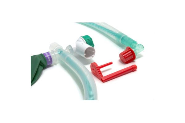
Co-axial Mapleson D - the Bain circuit
In the Mapleson D circuit, the fresh gas is delivered at the patient end of the circuit. In its coaxial form, this is easy to achieve by placing a small diameter hose within a normal 22mm breathing hose. Since the fresh-gas comes from a high-pressure source, resistance to flow is unimportant.
The Bain circuit presents one unique hazard; should the inner hose (green pipe in the figure below) become disconnected at the proximal end, then massive rebreathing will occur. Before use, the circuit must be checked and the disposable version of the circuit are often supplied with a testing device (see picture - red component). With fresh gas turned on, the inner hose is occluded at the patient end of the circuit. Provided that the circuit is intact, this should result in rapid pressure rise; if the inner host has become disconnected, then the fresh gas simply leaks into the expiratory circuit. An alternative check is to active the oxygen flush (patient-end of the circuit disconnected). The high-speed jet of gas emerging from the inner hose generates a low-pressure zone (Venturi effect), sucking gas from the outer hose and collapsing the reservoir bag. If the inner hose is disconnected, then the fresh gas enters the patient hoses at the proximal end and the circuit pressure rises, inflating the reservoir bag.
A circle system is just another breathing system ! This is not easy to appreciate because we are so used to having the circle built into the anaesthetic machine; they seem to be one and the same, but it is much easier to think of the machine and the circle as two entirely distinct pieces of apparatus.
A circle system always features unidirectional gas flow. To achieve this, the system contains one-way vales. Unsurprisingly, there is a connection to provide fresh gas.
Just as in the Mapleson circuits, there is a component which provides a gas reservoir - either a bag or bellows/piston which is under the control of a ventilator.
There must also be a way to release excess gas. In fact, there are at least two paths for gas to escape the system, one under manual control (an APL valve) and one which is under the control of the ventilator.
The purpose of a circle is economy. It allows the recirculation of the circuit gas i.e. rebreathing. This can only work if there is a means of removing CO2 and this is achieved by a chemical absorber as shown in the stylised arrangement below. N.B. rebreathing could be prevented simply by using a very high fresh gas flow - under these circumstances all of the expired gas is vented via the APL (or equivalent) valves. Whilst this defeats the purpose of a circle (i.e. economy) it is a useful thing to remember as it provides a fallback method of preventing the rebreathing of CO2 if the absorber becomes exhausted and cannot be replaced.
In drawing this system, remember that economy is the aim ! Start by drawing a circle and add a patient connector on one side. Place the CO2 absorber on the opposite side of the circle as this represents the transition between used CO2 containing and clean gas. Add one way valves which now define one limb as inspiratory (flow towards the patient) and one as expiratory (flow away from the patient).
There is no point in scrubbing any portion of the expired gas which is going to be sent to scavenging, so place the APL valve before the CO2 absorber. Similarly, there is no point in venting fresh gas, so that is introduced on the inspiratory side of the system.
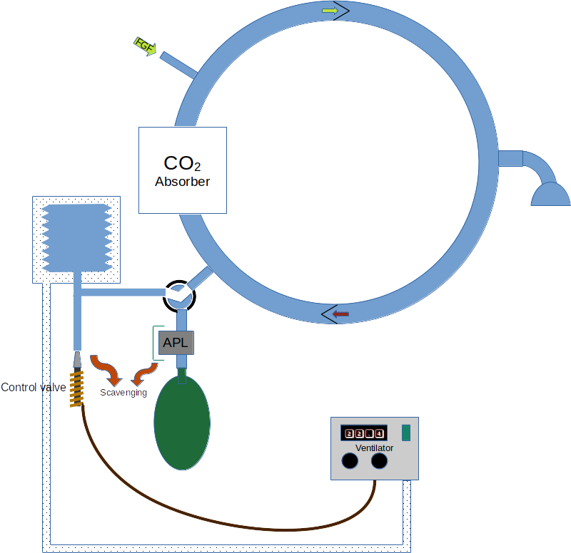
Now, were we able to exactly match the volume of CO2 removed from the circuit by the absorber with fresh gas, then there would be no gas discharged to scavenging. In this case, we have a fully closed system. In practice this is almost impossible; since the breathing system gas is recirculated, any tiny discrepancy between fresh gas supplied and CO2 absorbed becomes cumulative. Either the circuit volume slowly decreased (the bag or bellows gradually collapse) or gas must be discharged to scavenging to prevent a relentless pressure increase. As a result, circle system are generally operated as semi-closed breathing systems.
Advantages and disadvantages of circles
Advantages
It is possible to run a circle with very low fresh-gas flows. At the extreme, it is necessary only to provide the patient's minute oxygen consumption, but it is essential to remember that as the fresh-gas flow rate is reduced, the FiO2 must be increased so as to continue to deliver the patient's minute oxygen requirement; at the point of reaching closed circuit conditions, the FiO2 must be 100%.
As circuit gas recirculates the heat and moisture coming from the patient tends to be maintained. As a result, circles are perhaps better for patients, especially when undertaking long procedures. The exothermic process of CO2 absorption assists further.
Disadvantages
At low-flows, circle systems are inherently unstable. Gas concentrations tend to drift slowly and constant vigilance is required. Under low-flow conditions, the concentrations of inert gases in the circle (e.g. nitrogen) will remain stable and so there can be a significant disparity between the FGF O2 concentration and the circuit gas. If the fresh gas flow rate is too low on 100%, then the total gas volume in the circuit will decrease and the bag or bellows will collapse (a greater volume of CO2 is absorbed than oxygen supplied). Alternatively, if the fresh gas FiO2 is reduced, then although the circuit volume may be maintained, there will be a gradual diminution of oxygen concentration (replaced by nitrogen or nitrous oxide depending upon the what is in use) until an hypoxic mixture results. These changes can be very slow - a circle used at low flows is very unresponsive.
At the start of a volatile-based anaesthetic, there is a large concentration gradient between the circuit gas and the patient's tissues. As a result, the diffusion gradient across the lungs is great and the uptake of the agent is high - i.e. a lot of molecules of agent move from the circuit into the patient. This quantity of agent must be replaced. If the fresh-gas flow-rate is low, then to provide a large number of molecules in a small volume of gas, the fresh-gas agent concentration must be set high; for a soluble agent this may mean that the maximum vaporiser setting is inadequate and very low flows cannot be used until a degree of equilibrium has been achieved. Using insoluble agents allow flow-rates to be reduced much more rapidly.
At low flows, little gas leaves the system. As a result, any toxic compounds tend to persist. Historically, this applied to the agent trichloroethylene which, in the presence of alkali and heat can degrade into dichloroacetylene (causes cranial nerve lesions and encephalitis) and phosgene, which is a potent pulmonary irritant. As a result, trichloroethylene is contraindicated for use in circles. More recently, there have been concerns that Compound A (a degredation produce of Sevoflurane) may be detrimental. Inreality these concerns are probably misplaced. If soda-lime is dried, then harmful quantities of carbon monoxide can be produced. This only tends to be a risk if a circle is left unused for a significant period (e.g. overnight) with fresh-gas turned on.
The large system volume of a circle (many litres) means that it is difficult to change gas concentrations quickly. Very high flows are needed and even then the tendency of some of the components to adsorb volatiles may make it difficult to make a circle safe for patients suspected of MH.
More doi: 10.4103/0019-5049.120149